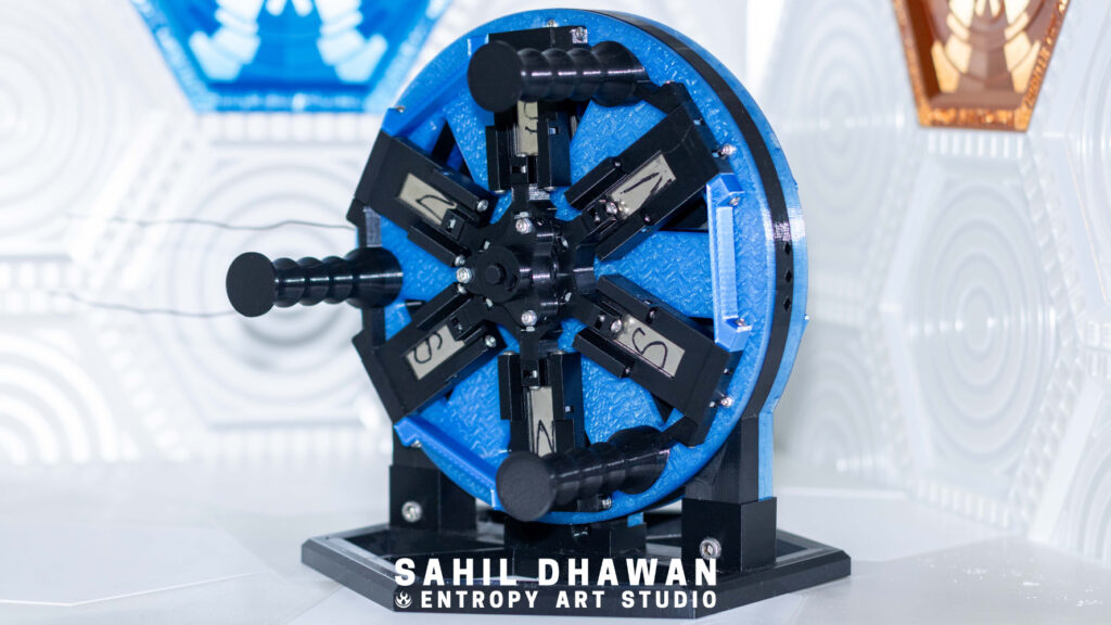
Contents:
- Motivation
- Lenz’s Law
- Designing Magnet Enclosures
- Copper Enclosure
- Creating a Serpentine Coil
- Test with a Multimeter
Motivation
I want to be completely self sufficient from energy companies someday but I know nothing about electricity.
I could watch a bunch of YouTube videos and read a lot of books on doing electrician work, designing circuits, and building generators. Instead I decided to do even more work by creating my own DIY Generator from scratch in FreeCAD so I could try to power a lightbulb.
I also wanted to design a system where I could try out multiple copper coil gauges and configurations to learn what works best in a generator and how the copper interacts with magnetism.
The generator is more of an education tool than an actual source of generating electricity in any useful way. I want to use it as a tool to lean and eventually teach how generators and electricity in general work.
Lenz’s Law
Electricity is the movement of electrons from one place to another. Lenz’s law is a fundamental property of physics that describes the direction of electric current in a conductor (the copper) created by a moving magnetic field (spinning magnets or moving a magnet through a copper circle).
When a magnetic current moves against a conductor, the conductor will try to resist the magnetic current by moving its electrons which creates it’s own magnetic field – the electrons move from one end of the copper wire to the other, with electrons coming out the end of the wire to create electricity for whatever device it is attached to.
A common misconception for people learning about electricity is that electricity moves through a wire at the speed of light. There is actually a formula to calculate how fast electrons move through a wire:
Where is the percentage of the speed of light in a vacuum in decimal form, and is the dielectric constant, or relative permittivity, of the medium (for example different gauges of copper) that the electricity passes through.
Designing Magnet Enclosures
Initial Design
For my first generator setup, I am using neodymium N52 magnets, which have a pull force of 12.22 kgs (26.95 lbs) with dimensions of 50.8 x 25.4 x 3.17 mm.
The magnets will be placed in a pattern that alternates the polarity (North and South) to generate a stronger magnetic field that moves through the copper.
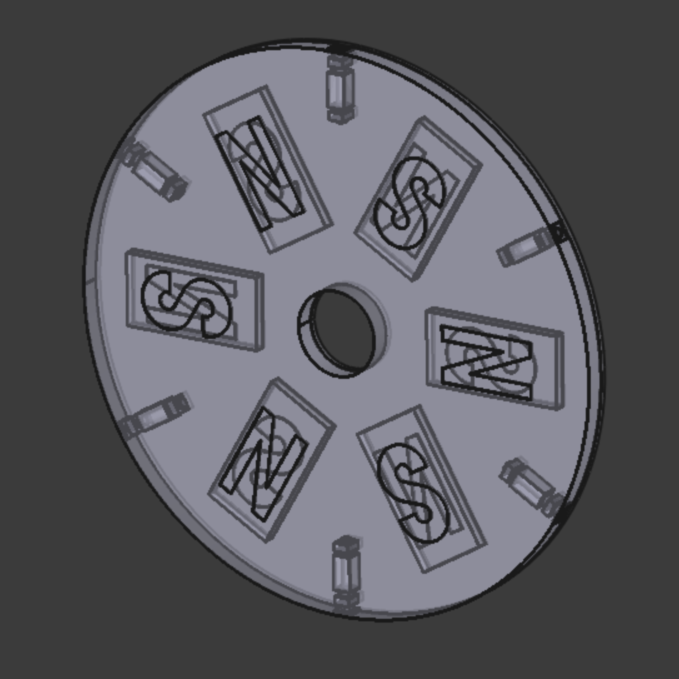
My initial idea for the magnet enclosure was to make a simple plate the magnets sit in with a cover that screws on top. I would then add attachment points for other parts of the generator assembly in a second version after testing if the magnets fit.
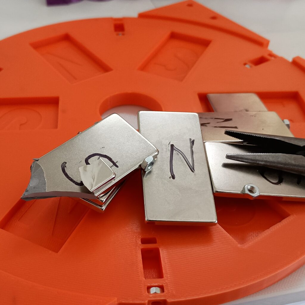
This is when I learned that apparently magnets can break in half:
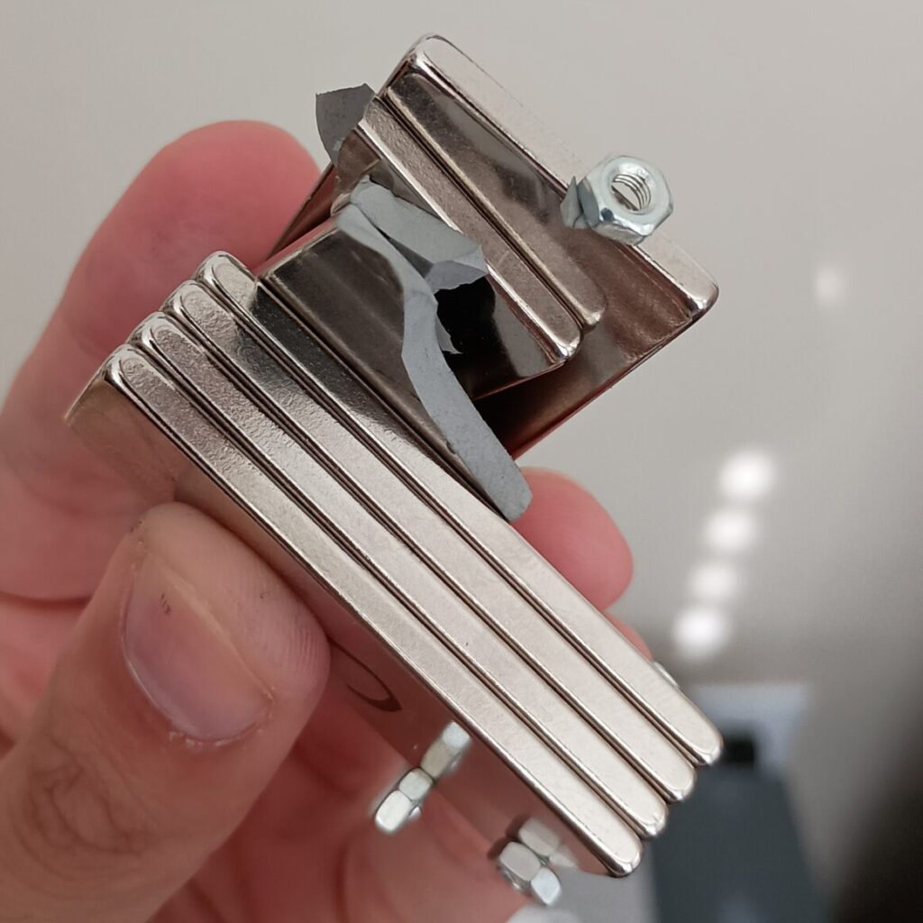
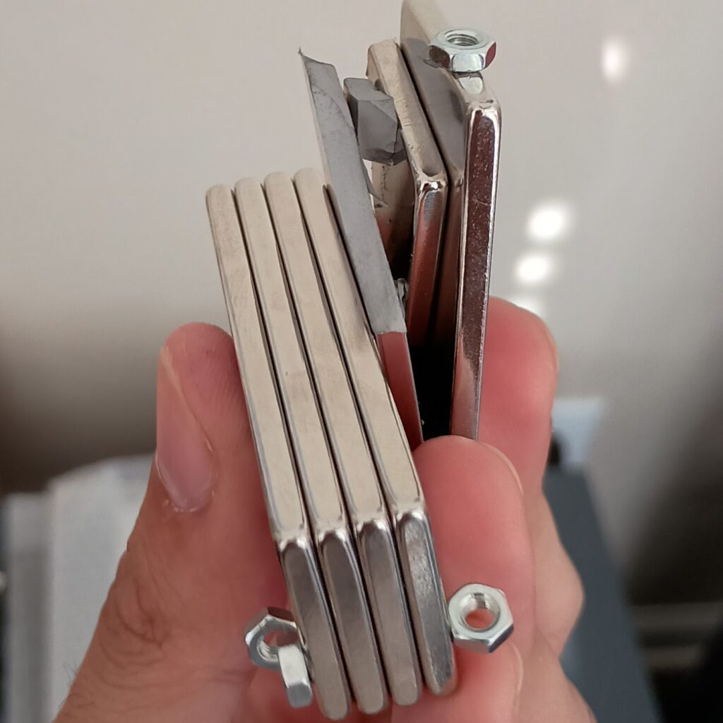
I did not design any way for the magnets to be easily pushed in or out of their perfectly toleranced indentations on the bottom plate. I also learned from trial and error that I needed to carefully slide the magnets into their positions instead of randomly placing my hand with the magnet in it over the plate with other magnets already in it. Two magnets attracted to the other I was holding in my hand so strongly that the force of them colliding caused one of them to snap in half when it hit my fingers.
If I never wanted to remove the magnets after screwing the top on, I would have designed the enclosure perfectly on my first try. However, this is a learning tool, so it needs to fit multiple types of magnets with different intensities, as long as they come in this specific size.
After finding out magnets can break and hurt my fingers, I tried hovering my pliers that came with my MK4S over one magnet while holding a finger over each of the other magnets to keep them from colliding.
This method of taking them out also caused one to break.
Purely out of spite and no other reason, I decided to try putting the remaining magnets plus extra magnets I ordered into place:
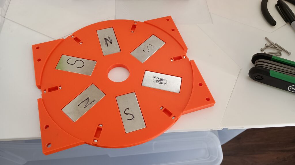
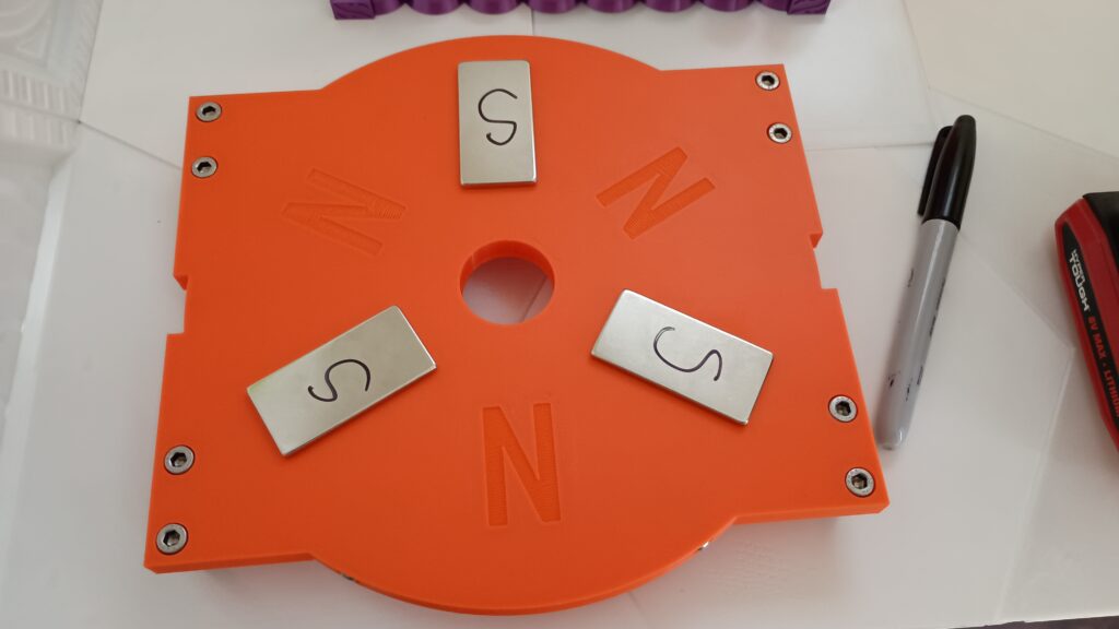
I had a total of 12 magnets by this point to create a magnetic field that connects on each side of the copper coil.
Reworking the Prototype
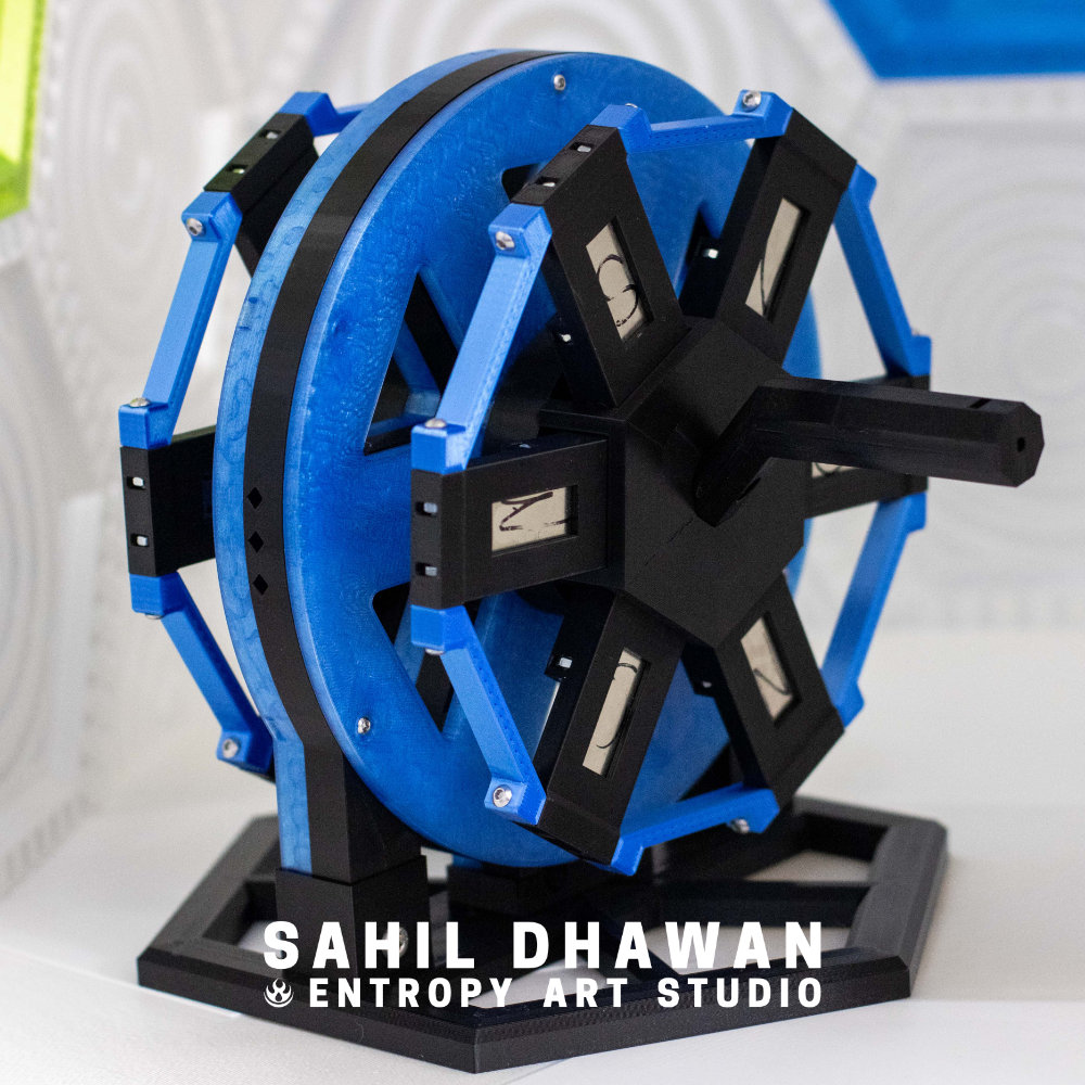
Instead of one big plate to hold all the magnets, I decided to create a small pocket for each magnet to slide into, and have all those pockets connect radially with two connection points on the edges and one in the center of the wheel, giving 3 points of stability.
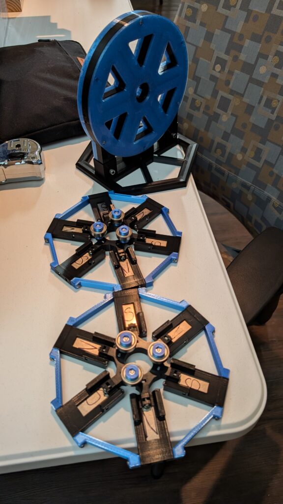
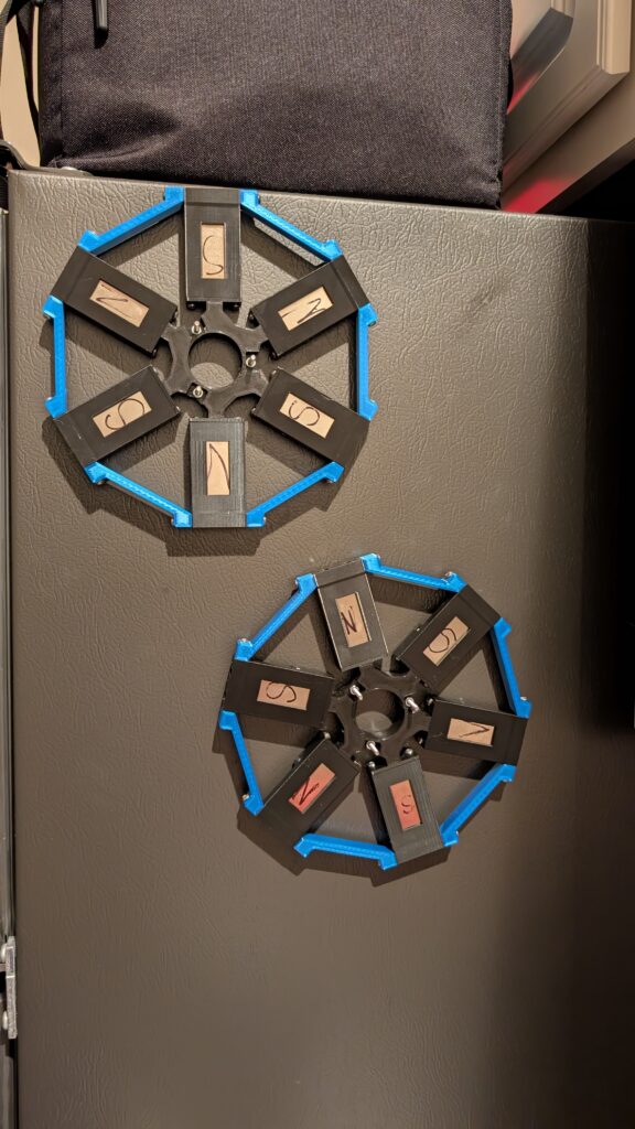
The new magnet enclosure uses bearings which will roll along the inside of a cylinder that is attached to the copper enclosure, while also being held in place with an axel.
Copper Enclosure
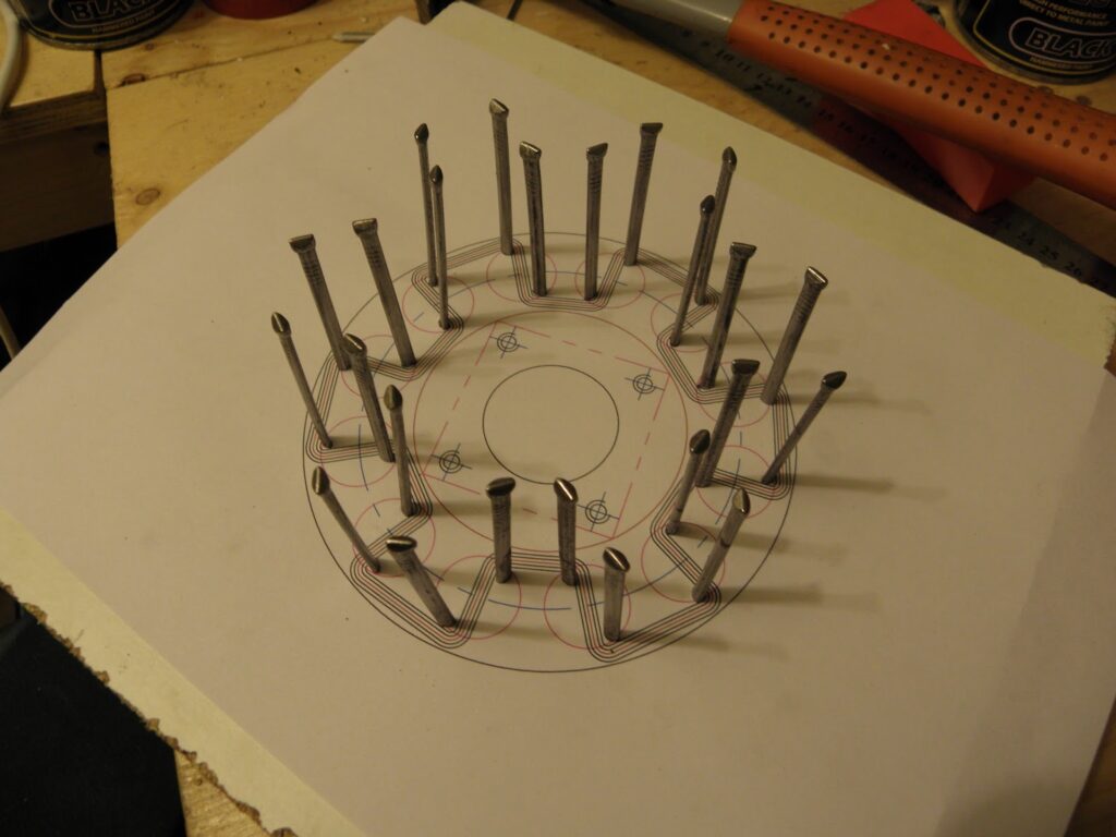
I found this image of a serpentine coil and transformed the image perspective so the circle would appear as if it were a flat circle generated by a graphic design program. I then overlayed a FreeCAD Sketch onto this image as a guide to creating the similar geometry and constraints for the main extrusion feature of this part.
Rest of the owl:
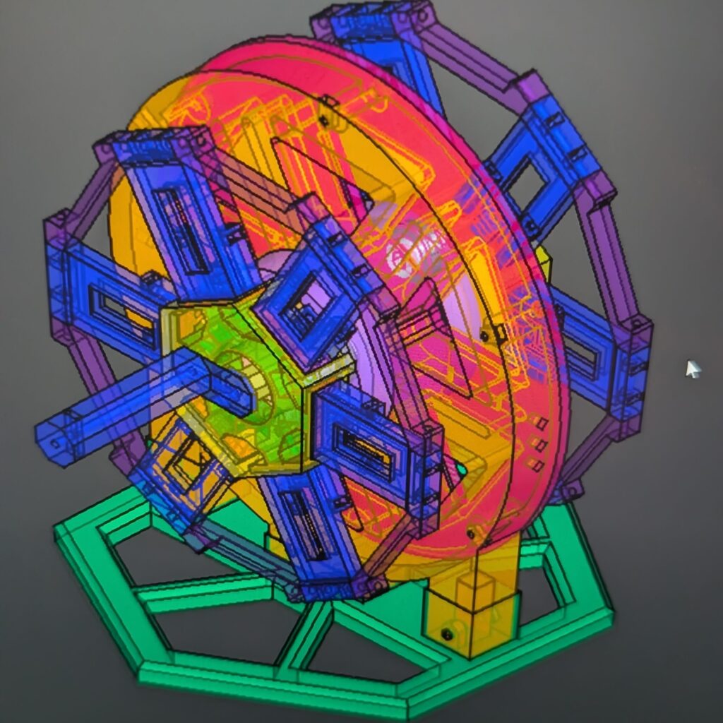
Creating a Serpentine Coil
Because I am making this generator both as a prototype and to learn what different gauges of wire do with different levels of magnetism, the actual gauge of wire I use doesn’t necessarily matter as long as everything can be assembled and generate some kind of electricity. I decided to start out with enameled 18 gauge copper wire after multiple searches showed it is common in general use cases and in lighting circuits.
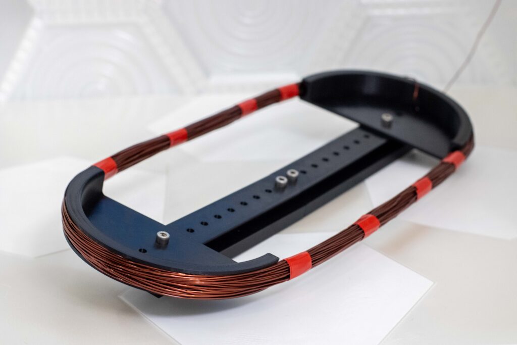
The picture above makes it look like it was easy to wind up the coil: it was not. Unlike Robert in his video, I had no clamp or vice to attach my coil winder to, so I held it in place with one hand or a foot while winding, with the starting end of the coil clamped into one of the M5 screws on the semicircle part of the jig.
I used electrical tape to keep the winded coil in place, re-wrapping it around the coil after more and more turns. Using electrical tape on this electrical project is just a coincidence and the most convenient tape I had on hand. Because the copper wire is enameled, it is shielded from itself and will not cause any arcing/sparks between coil layers when electricity is being generated.
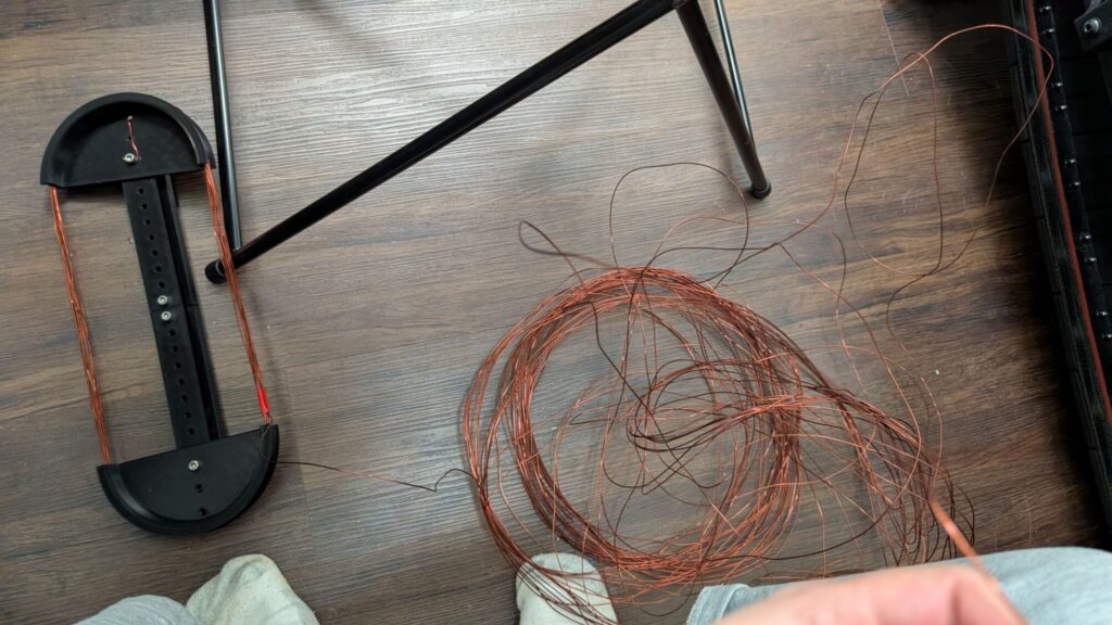
At some point more than half the wire fell off the jig. It also ended up getting tangled after falling off somehow, I lost many brain cells while untangling the wire in multiple areas.
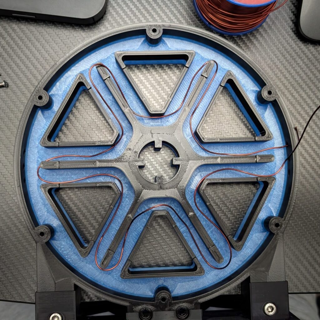
I used one pass of copper wire to make a rough estimate of the serpentine perimeter in the generator so I can figure out how far to extend the semicircles on the jig. I marked what the perimeter would be on the wire and used that to decide how far to extend the jig.
After what felt like days (2 hours), I finally got all of the coil winded around the jig. I molded the shape of the coil to the serpentine shape and placed it in the enclosure. However I would quickly discover a new problem.
I think I estimated wrong:
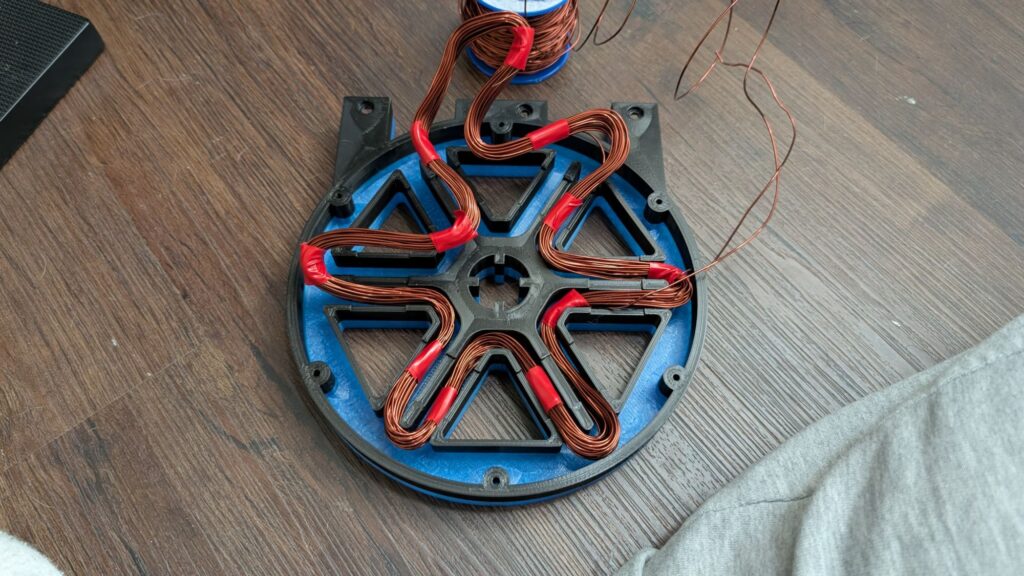
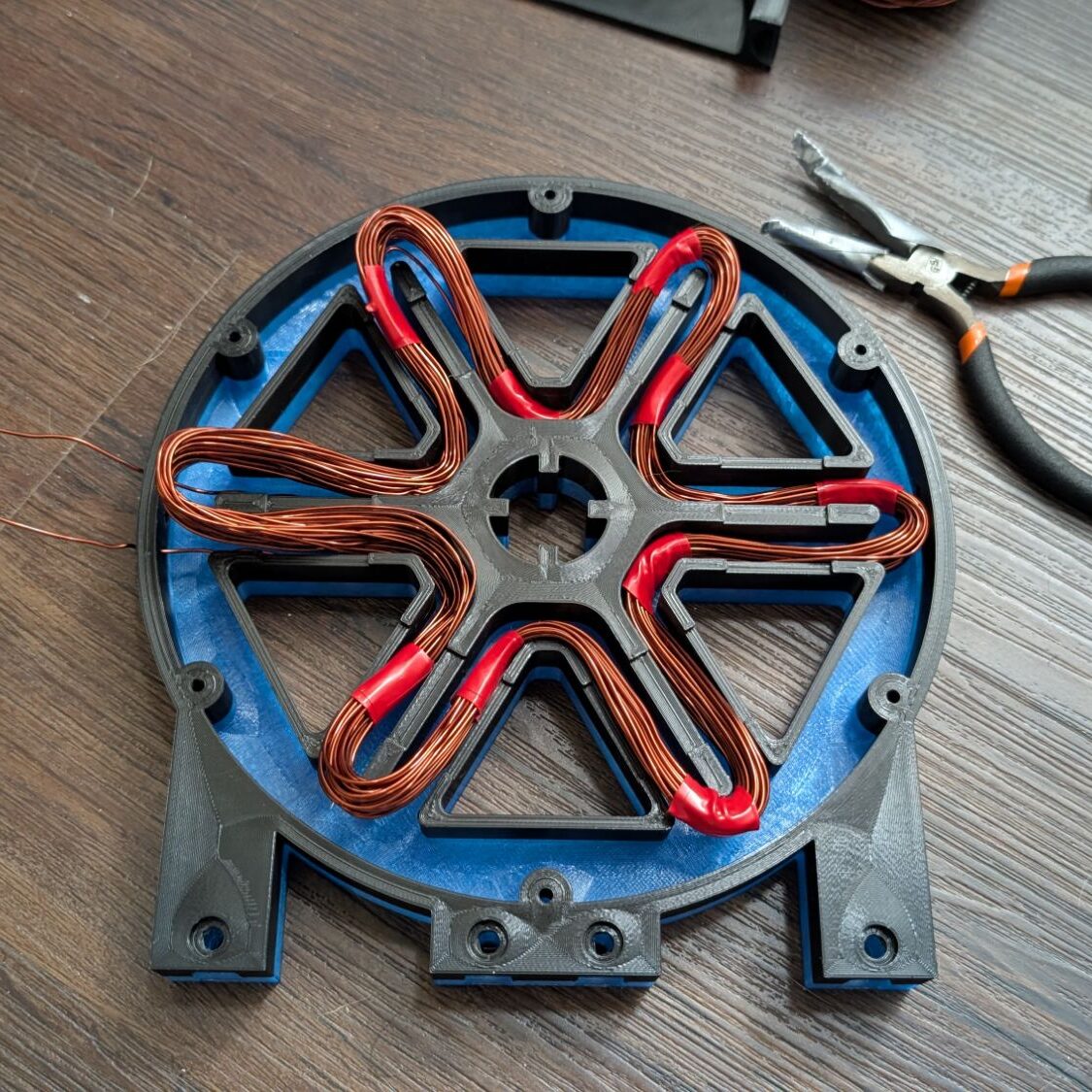
After adjusting the jig and doing the entire process again, I made a better estimate of the serpentine perimeter which was only slightly too large (it’s not the size it’s how you use it). I wrapped the pliers that came with my Prusa MK4S in duct tape to keep the copper wire enamel from getting damaged and to mold the coil into a serpentine shape. But mostly I used the pliers to jam the larger arm of extra copper into place.
Test with a Multimeter
(Pronounced mul-tim-iter)
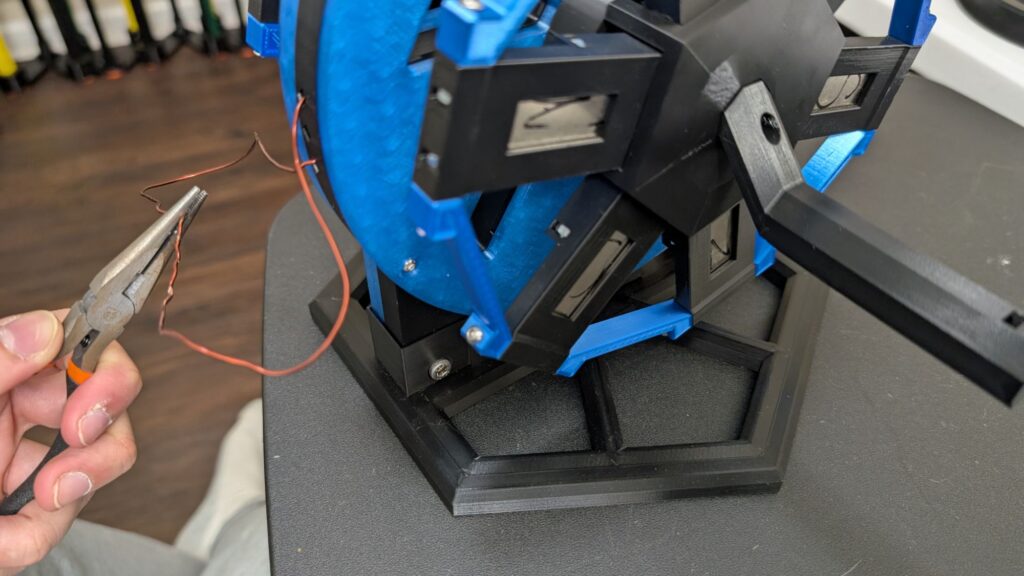
What would be the point of doing all this if I didn’t try to shock myself???
I held both ends of the copper wire between my finger and thumb while spinning the generator. I couldn’t film it and didn’t think to put my camera on a tripod to take a video because my brain was fried from winding the coils twice. Unfortunately I only felt a tiny spark and not much else while spinning the generator.
The next day I took the generator to the local makerspace to measure how much power it might be able to generate.
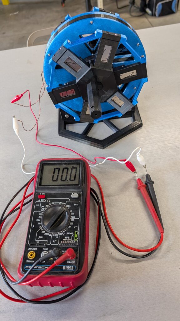
The measurements are in mV (milivolts) and fluctuate because I was not spinning the magnets at a constant rate. After filming this video, I found out the multimeter may have been old or faulty and the readings could be unreliable. This does not change the fact that spinning the magnets does create an effect, which is the outcome I was hoping for.
Small Improvements
I need to buy a USB-connected multimeter to run more accurate tests and measure output based on RPM. However, there were two clear issues that I could still fix even without more measurements:
- There is too much empty space between the copper coil and magnets.
- This causes the magnetic field passing through the copper to be more spread out and make Lenz’s law have less effect, causing a smaller amount of electricity to be generated.
- The electricity generated after this fix would likely still be in the milivolts either way, but it’s worth fixing this issue because it ties in well with fixing the second issue:
- As you can see in the video, I had trouble spinning the wheel with the handle in the center and had to roll it from the edges.
I made changes to the axel/hubcaps to remove the center handle, and modified the connector pieces on the outer edge of the magnet enclosures to include handles in the designs. The result is much more ergonomic and reduces the gap between the magnets and copper.