The Babies:
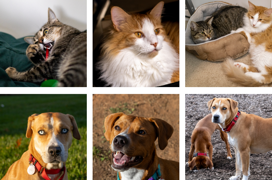
Problem: I want to create 3D models of my pets to print sculptures of them so I can hug the sculptures way in the future.
Solution: Create a very complicated and potentially over-engineered 3D scanner booth!
To do this, I first need to 3D scan my pets. This is not as easy as regular 3D scanning, however.
Traditional 3D scanning, or photogrammetry, involves taking multiple pictures of a still object or room and these 3D scans typically do not involve the subject moving at all. When it comes to 3D scanning pets, even a small movement of a cat’s head, ear twitch, or tail wiggle, could cause problems for the photogrammetry algorithm which creates a 3D model of the collection of pictures.
Photogrammetry with moving subjects requires the use of a 3D scanning booth, typically with many cameras in a cylindrical pattern around the subject. Usually, these booths are prohibitively expensive and are stuck in one room. I do not have $25,000+ and do not have a retail or office space to keep this scanner. I am attempting to solve both these problems by reducing the cost and allowing for portability through use of the following:
– Raspberry Pi’s and Pi Cameras
– 3D printed Pi Cases
– 3D printed collapsible and modular rig
– Aruba S2500 48P Power over Ethernet (PoE) switch
– A battery pack to provide power to the switch and LEDs
To start this project, I needed to first create the Raspberry Pi case and case bracket which would attach to the modular rig. I started designing each part of the camera module 4 months before writing this post and cannot remember every design decision that went into creating the assembly. Also, no one would read that, so here are the basic design points:
1. The ports of the Raspberry Pi need to be accessible in case a module needs troubleshooting. Also, I learned later in the project that the Pi PoE hat apparently cannot be powered by USB C ever while attached to the Pi, as this kills the PoE hat by short circuiting. Because of this, a plug needed to be created for the USB C port to prevent this mistake from happening again.
2. The Pi Camera needs to be positioned directly above its connection slot on the Pi, causing the connector cable to form an “S” shape. This is to prevent any crimping or folding of the connector cable which would happen in any other position.
3. The PoE hat includes a fan, so an exhaust port for this fan needs to be included as well as additional holes in the lid to allow for better airflow.
4. A print-in-place SD card door should also be included in case an SD card needs to be removed or replaced quickly.
5. The Pi Case needs to be contained within a bracket piece. This allows the Pi Camera to be centered when attached to the columns of the rig instead of offset to one side of the Pi Case. The bracket also allows for more freedom of connection points to the 3D Scanner Booth rig which has not been designed yet.
Taking the above points into consideration produces the camera modules and brackets below!
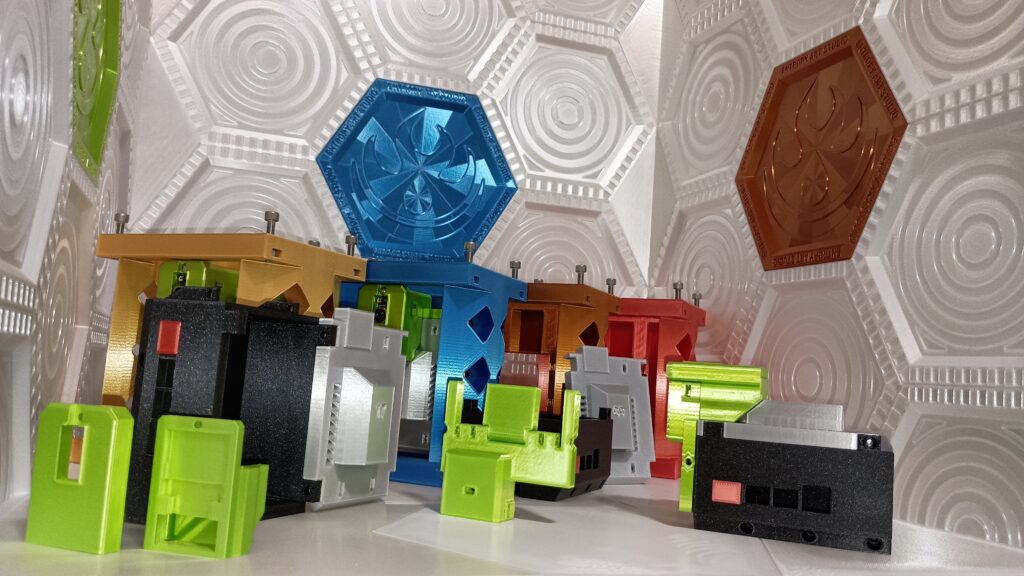
With these designs finished, the next halfway step is printing 24 of these modules. Most 3D Scanner Booths use 40 or more cameras. This eventually will be my setup as well, but with the correct lighting and placement of the cameras (more on this in a later post), 24 cameras should provide ideal results.